
Integrating Meshtastic LoRa Nodes with Home Assistant
Setting up a private mesh radio network using Heltec V3 nodes, 3D printing custom enclosures, and routing telemetry into a custom Home Assistant network dashboard.
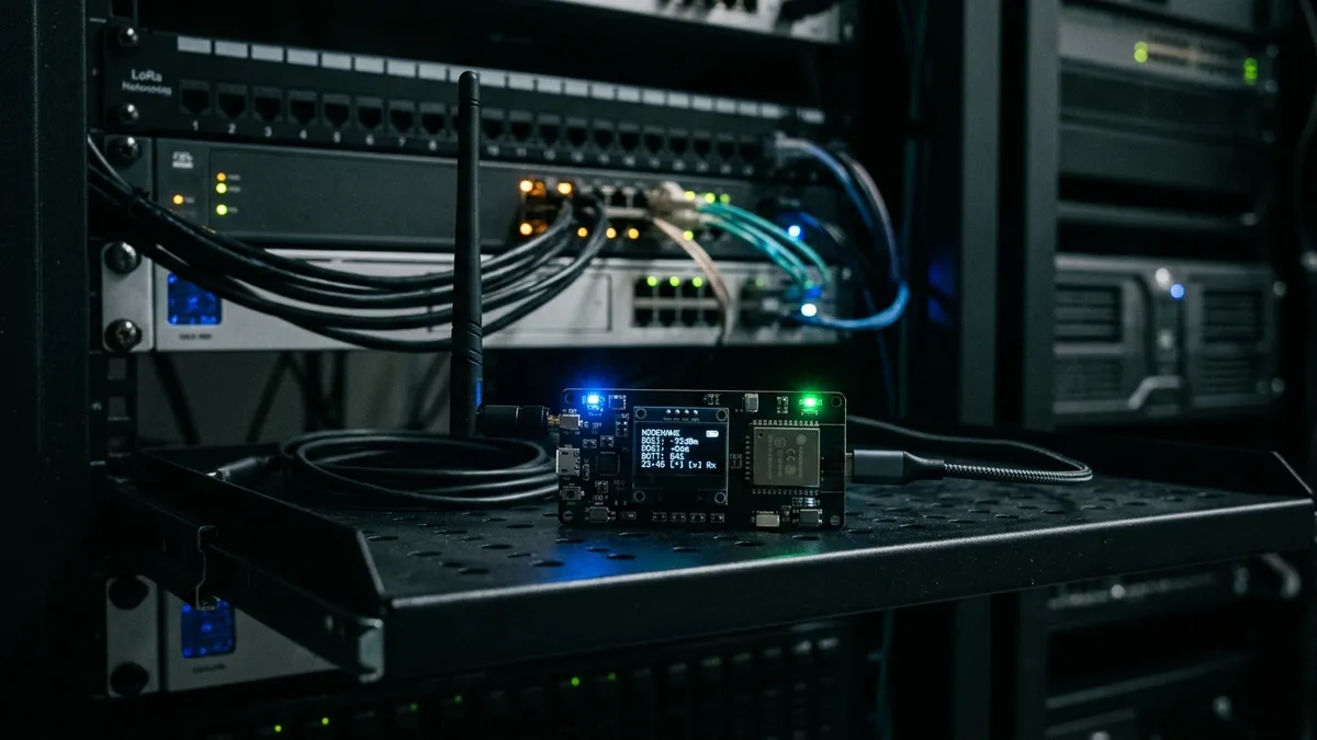
LoRa (Long Range) radio mesh networking has exploded in popularity, enabling completely decentralized, off-grid communication networks. Using Meshtastic, you can send text messages, share GPS locations, and route sensor telemetry across miles without relying on cellular towers or internet service providers.
Prerequisites
Before beginning the integration, ensure you have the following services configured:
- Home Assistant deployed on your local network. (See my guide on Deploying Home Assistant OS as a VM on VMware ESXi).
- Mosquitto MQTT Broker running on your home lab. (See my guide on Setting up a Mosquitto MQTT Broker in Docker).
In this log, I’ll walk through setting up my private Meshtastic nodes, 3D printing rugged enclosures, and integrating them into a custom Home Assistant dashboard to track local messages and manage node controls.
My Hardware Setup
I am running a two-node Meshtastic setup using Heltec V3 devices sourced from Meshnology:
- Wi-Fi Base Station (Home Unit -
CMS3): A stationary Heltec V3 node connected to my home Wi-Fi network. It acts as the gateway routing mesh traffic into Home Assistant. Since it is stationary and always powered, I can easily manage it over the local network using the browser-based Meshtastic Web Client. - Mobile Node (On-the-Go Unit): A portable Heltec V3 node that travels with me. It connects directly to my phone over Bluetooth via the Meshtastic Android Client App. It is housed in a custom 3D printed H1 Case printed in high-visibility orange filament.
- Case Design: H1 Case for Heltec V3 by TonySmarthome on Printables. This compact, rugged print provides protection and easy access to the buttons and OLED screen.
Parts List & Tools
| Part | Description | Source / Link |
|---|---|---|
| Heltec V3 Node | Meshnology LoRa 915MHz Dev Board with OLED | Meshnology Store |
| H1 Custom Case | Rugged 3D printed enclosure for Heltec V3 | Printables Model 741974 |
| 1100mAh LiPo Battery | Rechargeable Lithium Polymer pouch cell | Included in Heltec Case Set |
The Enclosure Build
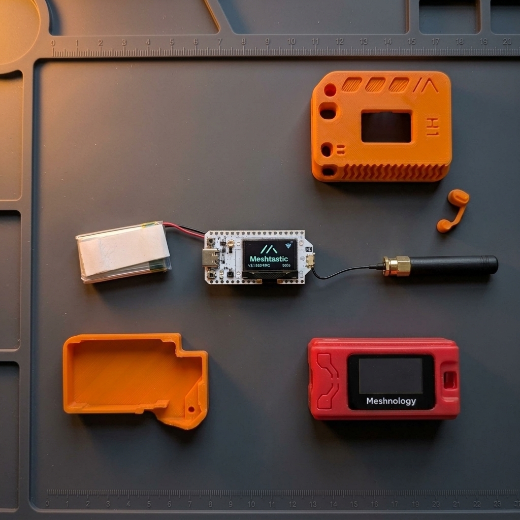 Teardown display showing the Heltec V3 development board, LiPo battery pack, pigtail antenna, original red Meshnology case, and the custom 3D-printed orange H1 case halves on a silicone tech mat.
I printed this H1 case in high-visibility orange filament. Interestingly, this print was one of the final projects run on my trusty old Ender 3 Pro printer before I upgraded my workshop to the new Creality K2 Pro.
The print turned out incredibly clean. The front shell features vertical chevron grip ridges, while the grey back plate snaps securely in place to protect the delicate Heltec V3 screen, battery contacts, and internal IPEX antenna connection.
Flashing the Firmware
Before assembling the nodes or mounting them in cases, you must flash the Meshtastic firmware onto the Heltec V3 microcontroller boards. The easiest way to do this is using the official browser-based Meshtastic Web Flasher (requires a WebUSB-compatible browser like Chrome, Edge, or Opera).
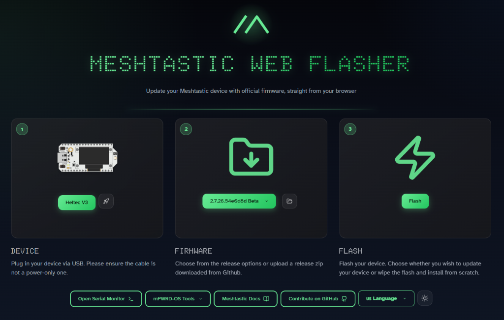 The Meshtastic Web Flasher interface showing the 3-step device configuration, firmware selection, and flash command portal.
Step-by-Step Flashing Guide:
- Connect the Board: Plug your Heltec V3 device into your computer using a high-quality USB-C cable.
[!IMPORTANT] Please ensure the cable supports data transfer; do not use a power-only charging cable.
- Select the Device (Step 1): Open the Meshtastic Web Flasher in your browser, and choose Heltec V3 from the device dropdown.
- Choose the Firmware Version (Step 2): Select the latest stable or beta firmware version from the dropdown menu (e.g.,
2.7.26Beta or Stable release). - Initiate the Flash (Step 3):
- Click the green Flash button.
- Select the serial port matching your connected Heltec V3 board in the browser pop-up window (typically labeled as
CP210x USB to UART BridgeorESP32-S3). - If doing a fresh install, select the option to Wipe Flash and Install from Scratch to clear any pre-existing factory test firmware.
- Keep the tab open and wait for the flash process to complete. Once finished, the Heltec V3 screen will light up with the Meshtastic boot screen!
 Home Assistant Integration
To bridge our stationary Heltec node (CMS3) with Home Assistant, we utilize the official custom integration available on HACS: meshtastic/home-assistant.
Step 1: Configure the Heltec Base Station
- Connect your PC to the same local network as the always-on stationary node.
- Open the local Meshtastic Web Client hosted on your Home Assistant instance at
https://<your_home_assistant_ip>:8123/meshtastic/web/index.htmlto configure settings. - Navigate to Module Settings -> MQTT:
- Enable MQTT: Toggle ON.
- MQTT Server Address: Enter your local Home Assistant MQTT broker IP (e.g.,
<your_home_assistant_ip>). - Encryption: Ensure JSON payload formatting is enabled for easy parsing.
Step 2: Set Up the Home Assistant Integration
- Open Home Assistant and navigate to HACS -> Integrations.
- Search for the custom repository Meshtastic and install it.
- Restart Home Assistant.
- Go to Settings -> Devices & Services -> Add Integration, search for Meshtastic, and configure it to point to your node’s local IP address.
Creating the Network Dashboard
I built a unified Home Assistant Lovelace dashboard tab named “Meshtastic Stats” to visualize active nodes in my mesh, track packet statistics, and manage text testing.
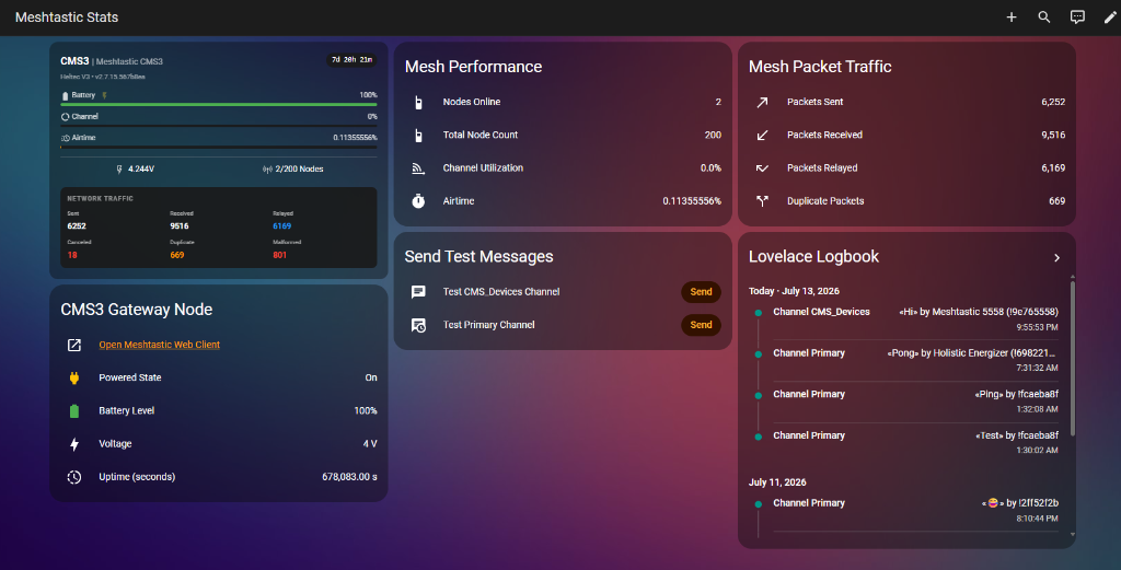 The finalized Meshtastic Stats dashboard in Home Assistant, featuring Gateway telemetry, performance statistics, packet traffic logs, test message trigger buttons, and a running message logbook.
Dashboard Column Breakdown:
- Gateway Node & Controls (Left Column):
- CMS3 Status Card: Displays the current status of the stationary base station, battery levels, voltage (
4.244V), airtime (0.11%), and active node counts (2/200). - CMS3 Gateway Node: Exposes diagnostic controls such as powered state, voltage, total uptime (
678,083.00 seconds), and a quick launch button directing users to the local Web Client.
- CMS3 Status Card: Displays the current status of the stationary base station, battery levels, voltage (
- Mesh Performance & Test Triggers (Middle Column):
- Mesh Performance: Shows real-time statistics of online nodes, total node count in the region, channel utilization, and current airtime.
- Send Test Messages (Test Buttons): Dedicated custom action buttons allowing you to send quick test packets (Test CMS_Devices Channel and Test Primary Channel) with a single tap. This is incredibly useful for verifying that your nodes are communicating properly and checking range coverage.
- Packet Traffic & Lovelace Logbook (Right Column):
- Mesh Packet Traffic: Displays running totals of Packets Sent, Received, Relayed, and Duplicates on the local mesh channels.
- Lovelace Logbook: Shows a chronological list of text messages received over the mesh (labeled by channel:
Channel PrimaryandChannel CMS_Devices), detailing the time and sending node ID (e.g.Heltec Energizer,Meshtastic 5558).
Controlling the Heltec Device & Testing Mesh Connectivity
The HACS integration maps standard command entities into Home Assistant, allowing you to manage the stationary base station directly from the dashboard. The most useful utility here is the Send Message (button.send_text) entity.
How to Run a Range and Connectivity Test:
- Trigger Outbound Broadcast: On your Home Assistant dashboard, type a test message in the input text box (e.g.,
"Range check from home server") and click the Send button. - Verify Gateway Broadcast: The command triggers Home Assistant to send the text payload to your stationary
CMS3base station, which immediately broadcasts it over the 915MHz LoRa frequency. - Check Mobile Node Reception: Observe your mobile node (housed in the orange H1 case) or open your phone’s Android client app connected over Bluetooth. You should see the message display on the Heltec V3’s physical OLED screen or inside the app chat feed. This confirms a successful outbound connection from your gateway to your mobile unit.
- Verify Inbound Logbook: Conversely, send a text from your mobile node via the Android app. Check your Home Assistant dashboard’s Lovelace Logbook card. If the message appears in the feed, it validates that your stationary gateway is successfully capturing inbound RF signals and routing the telemetry payload through MQTT into Home Assistant.
Conclusion and Future Steps
Integrating Meshtastic with Home Assistant bridges the gap between decentralized off-grid communications and local smart home automation. Having a stationary base station like CMS3 acting as a Wi-Fi-to-LoRa gateway ensures that even if external networks go down, your home hub remains connected to your portable nodes.
Moving forward, my next steps for this project include:
- Solar Node Deployment: Building a weatherproof, solar-powered node using a custom battery pack to place high on the roof line for better line-of-sight range.
- Antenna Upgrades: Swapping the default stubby antenna on the base station for a high-gain omnidirectional antenna mounted outdoors.
- Automated Alerting: Configuring Home Assistant automations to send critical system notifications (like UPS battery warnings or security alerts) over the LoRa mesh directly to my mobile node.
This setup proves that with a couple of budget-friendly Heltec V3 boards, some 3D-printed plastic, and the power of HACS integrations, you can build a robust, private radio network right from your home lab.